TRUSSES or FRAMES:
Hello mechons, in this post we are going to explain to you about a little topic of the Engineering mechanics called Frames also called as Trusses.
Before going to learn about the types of frames and its uses first we need to know about,
{tocify} $title={Contents}
What are Trusses or Frames?
A structure with several bars riveted or welded together are called Trusses or Frames. They basically provide strength and support to a construction.
To find the support reactions at the end, same principles as in beams are used,
- Analytical method
- Graphical method.
Types of frames
End supports of frames are differentiated as,
- Frames with simply supported ends.
- Frames with one free end and one hinged end.
- Frames with both end fixed.
Frames with simply supported ends:
In this case, it is same as simple support beam. Here, two simple supports are used at the ends. So, two vertical forces are considered at the two ends of the frame.
 |
| (Example for simple supported frame) |
 |
| (Free body diagram of simple supportrd frame) |
Problem:
 |
| (Fig-1.1) |
Frames with one end hinged (pin jointed) and other end freely supported on rollers
 |
| (Free body diagram) |
When a frame carries horizontal or inclined load, a pin joint and a free end is needed to compensate the load. Types of load applied on frames with hinged and roller end,
- Horizontal loading
- Inclined loading
Problem
 |
| (Fig 1.2) |
Frames with Horizontal Loading:
 |
| (Frames with horizontal loading) |
Here, ∑H = Algebric sum of Horizontal reactions,
∑V = Algebric sum of vertical reactions.
Problem:
Frames with Inclined Loading:
1. Analytical method
2. Graphical method
Problem
 |
| (Fig 1.4) |
 |
| (Graphical method) |
- First draw the free body diagram and name the forces and reactions according to BOCO's notations.
- Add the forces together and assume them to act together at C.G (CENTRE OF GRAVITY) at C.
- Draw the line of action of resultant force to meet at line of action of roller support.
- Join OA, from O cut off OM equal to toatal componded load (i.e. 4KN) along the line of action of resultant force.
- Complete parallelogram OLMN, with OM as diagonal.
- Measure ON and OL. The length OL gives the magnitude and direction of Reaction Ra and also Reaction Rb magnitude.
- By measuring, we get
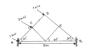
Frames with Both End Fixed
The assumptions are,
1. Reactions are parallel to direction of loads.
2. In case of Inclined loads, Horizontal thrust is equally shared between reactions.
Problem:
Example Problem for Frames with both ends fixed (Fig 1.5).
 |
| (Fig 1.5) |
Given data :
Span = 8m
Let Ra be Reaction at A and Rb be Reaction at B.
Solution
Assumption 1:
Reactions are parallel to the direction of loads
Equating moments at A,
Rb x 8sin60°= (2x2/Cos30°) + (1x4/Cos30°)
Rb x 8 x 0.866 = 9. 24
Rb = 9.24 / (8x0.866)
Rb = 1.33KN
Ra =(1+2+1) - 1.33
Ra = 2.67KN
Assumption 2 :
Horizontal thrust is equally shared by reactions.
Total horizontal component of load,
EH = 1cos60° + 2cos60° + 1cos60°
EH = 2KN
Horizontal thrust on each support,
Rah = Rbh = 2/2 KN = 1KN
Now, Equating clockwise and anticlockwise moments about A,
RBV x 8 = (2x2/cos30°) + (1x4/cos30°)
= 8/0.866
RBV = 9.24 /8
RBV = 1.15 KN
RAV = [ 1sin60° + 2sin60° + 1sin60°] - 1.15 KN
RAV = 2.31 KN
Ra = {(1)^2 + (2.31)^2}^1/2
Ra = 2.52KN
tan ंa = 2.31/ 1 =2.31
ं a = 66.6°
Similarly, Rb = ((1)^2 + (1.15)^2)^1/2
tan ं b =1.15/1 = 1.15
ं b =49°
Conclusion
That's all about the frames or trusses types, forumulae, and example problems in frames for now. I hope that you understand the definitions, formulae and types.
If you have any queries or doubts regarding this topic don't hesitate put that in the below-mentioned comments section. We are here for you we will reply as fast as possible.
And one more thing Always remember to
Spark your brain and Throttle your knowledge!.


